Comparators and Signal Conditioning
Real sensors rarely connect directly to digital inputs or ADC pins. A practical interface often needs a comparator for decisions, hysteresis for clean switching, and signal-conditioning stages for gain, filtering, buffering, and level shifting.
Learning Objectives
By the end of this lesson, you should be able to explain comparator action, add hysteresis, calculate a simple hysteresis window, design a basic sensor-conditioning chain, and identify common causes of noisy or unreliable analog inputs.
Comparator Action
A comparator answers one question: is one voltage higher than another?
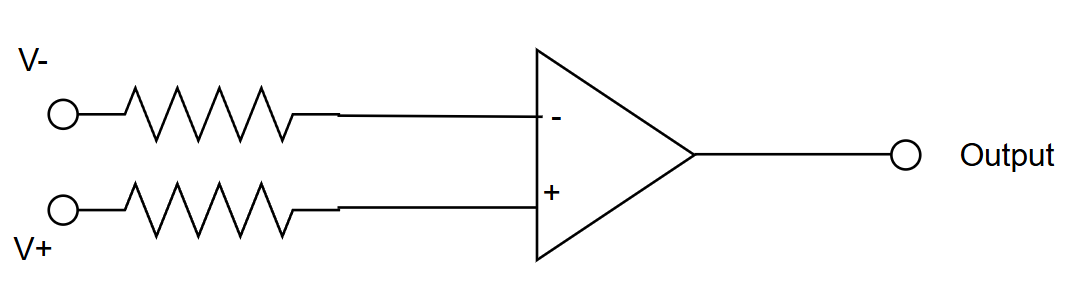
For a non-inverting comparator:
- if (V_+ > V_-), output goes high;
- if (V_+ < V_-), output goes low.
An op-amp used open-loop can behave like a comparator, but a real comparator IC is usually better for digital decisions because it has faster recovery from saturation, defined output stages, and logic-friendly behavior.
Threshold Example
A temperature sensor produces (10\text{ mV}/^\circ\text{C}). You want an alarm at (30^\circ\text{C}).
[
V_{TH}=30 \times 10\text{ mV}=300\text{ mV}
]
Connect the sensor to one comparator input and a 300 mV reference to the other. The output changes state when the sensor crosses the threshold.
Noise and Chatter
Near the threshold, small noise can repeatedly toggle the output:
This is chatter. It is common with slow sensors, long wires, motor noise, switch bounce, and ripple on the reference voltage.
Hysteresis
Hysteresis adds two thresholds instead of one:
- upper threshold (V_{TH}) for switching one way;
- lower threshold (V_{TL}) for switching back.
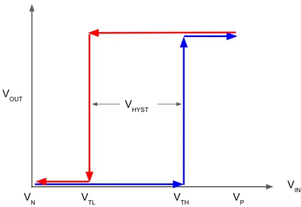
The hysteresis width is:
[
\Delta V_H = V_{TH}-V_{TL}
]
If an over-temperature alarm turns on at 300 mV and off at 280 mV:
[
\Delta V_H=300\text{ mV}-280\text{ mV}=20\text{ mV}
]
Noise smaller than the hysteresis window no longer causes repeated switching.
Positive Feedback Divider
Hysteresis is created by feeding a controlled fraction of output voltage back to the threshold node.
For a simple Schmitt arrangement where the feedback fraction is (\beta):
[
\beta=\frac{R_{LOW}}{R_{TOP}+R_{LOW}}
]
The approximate hysteresis width is:
[
\Delta V_H \approx \beta(V_{OH}-V_{OL})
]
where (V_{OH}) and (V_{OL}) are the actual comparator high and low output voltages. Use actual output levels, not ideal supply rails, when accuracy matters.
Worked Hysteresis Example
Suppose:
- comparator output swings from (0.1\text{ V}) to (4.9\text{ V});
- desired hysteresis width is (100\text{ mV}).
[
\beta=\frac{\Delta V_H}{V_{OH}-V_{OL}}=\frac{0.1}{4.8}=0.0208
]
A convenient divider near this ratio is (R_{LOW}=10\text{ k}\Omega), (R_{TOP}=470\text{ k}\Omega).
The exact thresholds depend on whether the input is applied to the inverting or non-inverting input and where the reference source is connected, so always verify the chosen topology.
Signal Conditioning Chain
Signal conditioning prepares a physical signal for a comparator or ADC.
Common stages:
- protection against ESD, overvoltage, and cable faults;
- filtering to reduce noise and aliasing;
- gain to use the ADC range;
- level shifting for bipolar or offset signals;
- buffering so the source is not loaded.
RC Filter
A simple first-order RC low-pass filter has cutoff frequency:
[
f_C=\frac{1}{2\pi RC}
]
For (R=10\text{ k}\Omega) and (C=100\text{ nF}):
[
f_C=\frac{1}{2\pi(10000)(100\text{ nF})}\approx159\text{ Hz}
]
This is suitable for many slow sensors, but not for fast control loops or high-speed measurements.
ADC Scaling Example
A pressure sensor gives (0\text{ V}) to (100\text{ mV}), and an ADC accepts (0\text{ V}) to (3.3\text{ V}).
[
A_V=\frac{3.3\text{ V}}{100\text{ mV}}=33
]
The amplifier, reference, offset, and output swing must all support the full range. If the op-amp cannot reach 3.3 V at the output, design for a smaller full-scale voltage or choose a rail-to-rail output device with adequate load margin.
Practical Checks
- Add hysteresis to slow or noisy comparator inputs.
- Check comparator output type: push-pull, open-drain, or open-collector.
- Ensure pull-up voltage matches the receiving logic.
- Filter before the ADC, but keep source impedance within ADC acquisition limits.
- Protect external inputs before the signal travels across the board.
- Confirm the reference voltage is stable and low noise enough.
Common Mistakes
- Using an op-amp as a comparator without checking recovery and output behavior.
- Setting only one threshold for a noisy mechanical or sensor signal.
- Forgetting that open-drain comparator outputs need pull-up resistors.
- Filtering so heavily that the control system reacts too slowly.
- Driving an ADC from a high-impedance divider without a buffer or acquisition-time check.
Summary
Comparators convert analog levels into decisions. Hysteresis makes those decisions stable. Signal conditioning makes sensor outputs safe, scaled, filtered, and low-impedance enough for ADCs or digital inputs. The reliable design is not one block; it is the chain from sensor to protection to filtering to gain to final input.
Further Reading
- Texas Instruments, "Comparator with Hysteresis Reference Design."
- Analog Devices, "Signal Conditioning for High Resolution ADCs."
- Microchip, "Comparator Tips and Tricks."